Optimizing a Wingbox Using Abaqus
Understanding how different ways of FEA modelling can affect your results
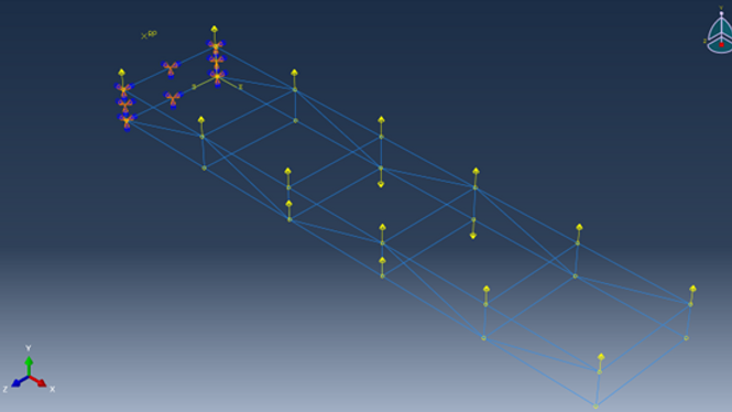
Given the load application on the left, create a wingbox to ensure stress and deformation are reasonable. See how using deferent FEA elements to model it affects results. Finally, optimize your design for load/weight ratio.
Problem Statement

On the right we see the results of the beam wingbox and associated Von Mises stresses. The location of maximum stress is shown in red near the base of the wingbox and is 154.4 Mpa where the maximum displacement is 87.67mm.
Beam Element Model
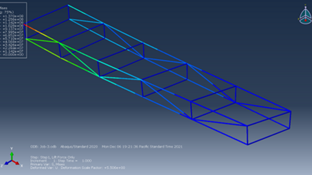
On the left we see the results of the truss wingbox and associated Von Mises stresses. The location of maximum stress is shown in red near the base of the wingbox and is 137.0 Mpa where the maximum displacement is 90.88mm.
Truss Element Model

Interestingly, although max stress is higher for the beam element, deflection is less. This can be explained by the moment load applied and how it handled different from beam and truss elements. Ideally, a combination and beams and trusses would be used with their appropriate loading designations. However, this allows for a rough comparison.
Comparison of Truss and Beam
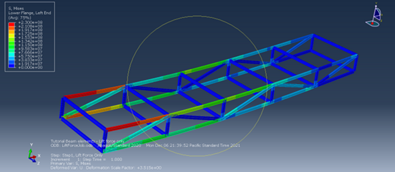
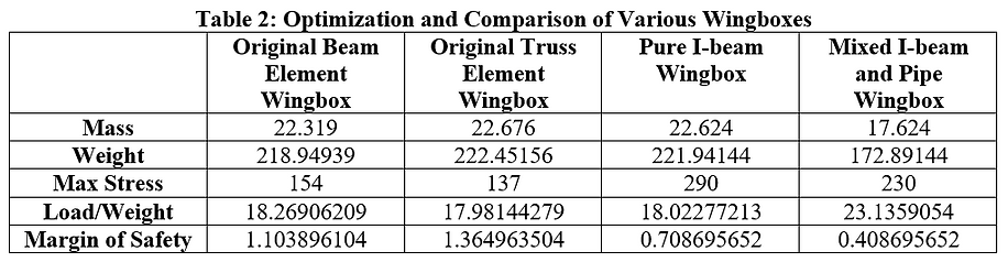
After tinkering around for a while this was the most optimal design purely on the criteria of stress, displacement and weight. A combination of I-beams for there strength, and Pipes for there lighter weight were used. For an actual wingbox design you must consider other important factors like cost, manufacturing, materials, etc. The table below shows final results with a foal margin of safety of ~0.5 (typical aircraft industry standard).
Optimal Design: I-Beams and Pipes